


In this research we propose a method of evaluating the load acting on the road-machine hydraulic-drive steering when the working tool hits a massive obstacle during its penetrating into the soil. Based on the analysis of the folding mechanism operation, this method allows evaluating the level of load acting on the hydraulic drive.
When a loader stops abruptly, its rear half-frame (power module) turns relative to the axis of the lag hinge at an angle j2..This involves a sharp pressure jump in the hydraulic drive of the steering mechanism. In the analytical model, equivalent springs with rigidity С1, С2 are used instead of hydraulic cylinders. The rigidity of ЦС-80-type steering hydraulic drive is assumed to be 2106 newton-meters.
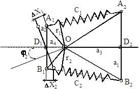
Fig. 1 Analytical model for determining pressure
When the system deviates at corner j2, a yaw moment М emerges.
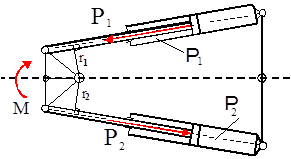
Fig. 2. Analytical model for determining pressure
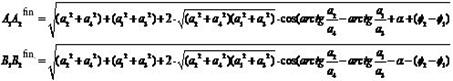
Efforts acting on hydraulic cylinders and expressed through rigidity and deformation are evaluated by dependencies:
 ,
,
where С1, С2 — rigidities,
 ,
,  - deformation of hydraulic cylinders.
Efforts acting on hydraulic cylinders and expressed through pressure and liquid sectional area are evaluated by dependencies:

where S1, S2 — rod end and head end.
The moment operates in the turning mechanism through efforts. A yaw moment replacing the action of the springs with rigidities С1, С2 can be expressed through a circular rigidity of the formation mechanism and angular deformation :
:
 ,
,
where СА — circular rigidity of the folding mechanism,
j2–1 — angular deformation of the folding mechanism.
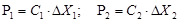
In the general case, circular rigidity is non-linear and depends on the angle of half-frame folding, but the calculations use an averaged value. This assumption is substantiated by the fact that the differences in the work area 0...15 ° do not exceed 10 %. For pressure evaluation, certain geometric parameters of the steering were determined.
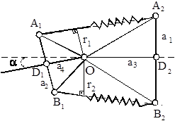
Fig. 3. Analytical model for determining geometrical parameters of the steering mechanism
 ,
,
 ,
,
 .
.
Variations in the length of hydraulic cylinders are determined making use of the theorem of cosines, and then we obtain:
- for the upper hydraulic cylinder working on tension
 ,
,
- for the lower hydraulic cylinder working on compression
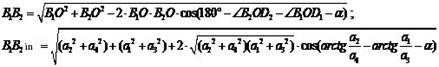
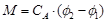
The finite value of a variation in the hydraulic-cylinder length is determined by angular deformation caused by inertia forces. The value is determined by dependence:
Thus, deformation of hydraulic cylinders is determined:
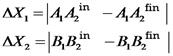 .
.
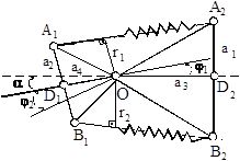
Fig. 4. Analytical model for determining variations in the length of the hydraulic cylinders
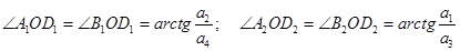
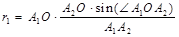
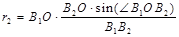
Using the theorem of sines, arm reach r1 і r2 is determined:
 ;
;
 ;
;  .
.
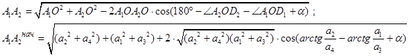
Having done the comprehensive analysis of geometry of the folding mechanism, we obtain dependence for determining pressure in the hydraulic drive of the steering mechanism:
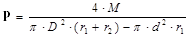
where M- circular moment of the folding mechanism,
D- piston diameter,
d — hydraulic-drive stem diameter.
The developed method was used for evaluation of steering hydraulic-drive load level at the moment of loader-bucket working tool penetration into the soil.
Figure 5 presents the dependence of pressure variation in the hydraulic drive of the control mechanism vs. the half-frame folding angle. The external interaction, i.e. digging resistance Wк was applied in the centre of the bucket (central impact В = 0). The following values were assumed as permanent:
the initial rate of movement Vn = 1 m/sec;
circular rigidity of the folding mechanism Са = 245 kNm/rad;
СРО — the rigidity of implements 1000 кN/m.
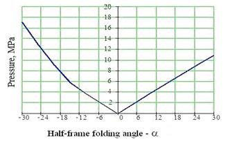
Fig. 5 Dependence of pressure variation in the hydraulic drive of the control mechanism vs. the half-frame folding angle
Figure 6 The time dependence of pressure variation in the hydraulic drive when applying the external load on the bucket edge and angles a =5°, a=15°
In this case, variation in pressure values at positive and negative angular values a (the latter varied from — 30° to +30°). The pressure grows as the value of angle a increases.
The most unfavourable cases (in terms of the hydraulic-drive load) are those when the worst angular effects between semi-frames a and the place of digging resistance application on the bucket join together.
One of such cases is presented in Figure 6. Figure 6a shows the bucket edge-obstacle interaction and 15°- angle of half-frame folding. The first peak corresponds to the impact, at this moment the pressure is 32 MPa. In Figures 6a, 6b the circled areas indicate the effect made by low frequency caused by oscillations of implements. Low frequency of oscillations is k= 23.57 s-1 with a period Т=0.267 s. High frequency k=4.83 с-1 has a period Т=1.3 s, position b, thus demonstrating the nature of the process with increasing angle a. As a increases, the period of oscillation becomes longer, e.g., if a =5°, Т1=0.99 s, then at a=15°, Т2=1.3 s.
During the research, factors affecting hydraulic-drive load were arranged. In the general case, the pressure depends on the followings factors: Р=f (B,a, Vn, CA, Сtl,Сir) where B — coordinate of digging resistance application; a- angle between semi-frames; Vn- the initial rate; СА- circular rigidity of the folding mechanism; Сtl- the lateral rigidity of buses Сir — the rigidity of implements. When the significance of the factor was determined, its maximum and minimum values were assessed, and their percentage ratio was specified.
