


The paper examines the design features of the microwave operational amplifiers (Op Amps) with differential input and output which have a near-zero output common-mode voltage.
Key words: operational amplifiers, differential stages, static mode.
I. INTRODUCTION
The application of the differential output in the operational amplifiers (Op Amps) allows to reduce the effect of the common-mode noise and the level of the second harmonic in the output signal spectrum, to almost double the maximum amplitude of the output voltage, to reduce the effect of “infiltration” of digital signals through the substrate in the analog-digital chips. Therefore, it is important to design such Op Amps.
The present paper deals with some methods for stabilizing the static mode of Op Amps with the differential output providing a near-zero static output voltage.
II. METHOD TO ENSURE A ZERO OUTPUT COMMON-MODE VOLTAGE IN OPERATIONAL AMPLIFIERS WITH THE OUTPUT EMITTER FOLLOWERS
The architecture of fig. 1 realizes a zero level of the output static voltage due to the feedback at the input stage. It facilitates AM matching with the subsequent stages.
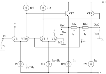
Fig.1. Architecture of the operational amplifier with the feedback to the common-mode signal at the input stage
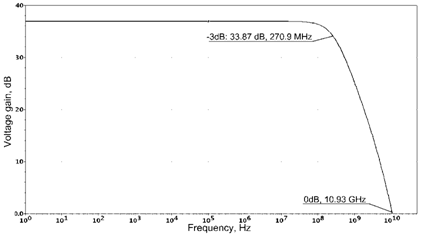
Fig.2. Frequency response function of the op amp for the models of FSUE NPP “Pulsar” integral transistors
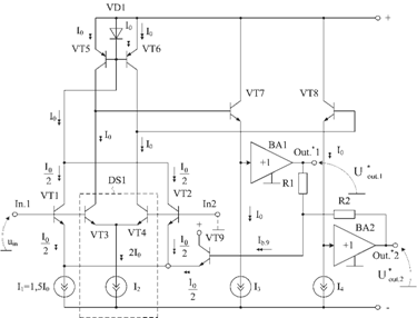
Fig.3. The first modification of the operational amplifier
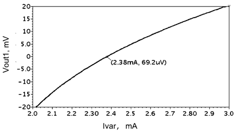
Fig.4. The dependence of the constant component of the output common-mode static voltage of Op Amps on the current I1=Ivar when impedance of the feedback resistors is R1=R2=1kOhm
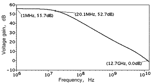
Fig.5. Frequency dependence of the Op Amp voltage gain
III. METHOD FOR STABILIZATION OF THE STATIC MODE IN THE OPERATIONAL AMPLIFIERS WITH THE PARAPHASE RAIL-TO-RAIL OUTPUT
In amplifiers with rail-to rail output the feedback at the input stage can be realized according to fig.6.
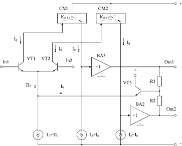
Fig.6. Architecture of Op Amps (P4227)
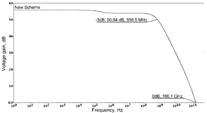
Fig.7. Logarithmic frequency response function of Op Amps in fig.6 based on the models of SiGe integral transistors
IV. OPERATIONAL AMPLIFIERS WITH CIRCUITS CANCELING THE EFFECT OF COLLECTOR LOAD RESISTORS ON THE VOLTAGE GAIN
When low-impedance resistors R1, R2 are used it is possible to neutralize them at the input differential stage (fig. 8).
The circuit in fig. 8 is based on the differential stages (DS) of transistors VT1, VT2 and VT3, VT4 with current mirrors CM1 and CM2. When using resistors with relatively low impedance R1=R2=R3=R4=R0=0,5÷1 kOhm each DS can have voltage gain of up to 40–80 dB [3, p. 4]. This effect of the voltage gain is explained by cancelling effect of resistors R1 and R2, R3 and R4 impedance which, however, depends on the current transfer ratio of the current mirrors CM1, CM2 and the voltage gain (Kу = 0,99–0.999) of the emitter followers of transistors VT7, VT8.
Frequency response function of Op Amps in fig.8 is shown in fig.9.
For the SiCe SGB25VD technical process the Op Amp architecture shown in fig. 8 is perspective. It is based on the canceling effect of collector load resistors R1=R2=R3=R4=R0 [3, p. 2].
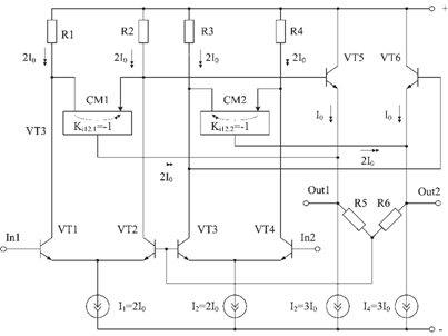
Fig.8. Op Amp architecture with R1, R2 (R3, R4) cancellation circuits
For this purpose current repeater circuits based on the traditional circuits are used. The efficiency of the method for increasing voltage gain depends on the rational design of the subcircuits CM1, CM2 when small voltages are used.
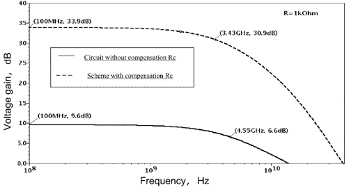
Fig.9. Dependence of the voltage gain on the frequency of Op Amps circuits with compensation R1, R2, R3, R4 and without compensation
The limited voltage gain of such Op Amps is defined by the accuracy parameters CM1, CM2 (Ki12.1 = 1, Ki12.2 = 1) and the error of the emitter followers VT8, VT7, which should be small.
V. CONCLUSION
The study of the basic modifications of the differential operational amplifiers with the circuits for stabilizing the zero level of the output common-mode voltage has shown that they can serve as a basis to create microwave circuits of OP Amps with the range of operating frequencies of up to 20–30 GHz when applying SG25VD and SG25H1 technologies.
Applying the principles of the self- and mutual compensation of the impedance in the circuitry of Op Amps of the given class as well as the above technologies of applying the negative feedback to the common-mode signal allows to further improve them due to their structural redundancy taking into account the technological limitations concerning their basic components.
References:
1. Microwave The IP-blocks of communication systems based on the fully differential operational amplifiers / N. N. Prokopenko, A. S. Budyakov, V. V. Suvorov, C. Scheytt / / The problems of developing advanced micro and nanoelekelectron systems-2010. The collection of works / under the total. Reduction of Academician AL Stempkovsky. — M.: IPPM RAS, 2010. — S. 583–586
2. Дифференциальный усилитель с повышенным коэффициентом усиления [Текст]: заявка на патент Российской Федерации; МПК8 H 03 F 3/34, 3/45. / Прокопенко Н. Н., Будяков П. С., Суворов В. В. — № 2009138961/09; заявл. 12.10.2009 (259).
3. The differential amplifier with the output paraphase: an application for the patent of the Russian Federation; IPC 8 H 03 F 3 / 45. / Prokopenko N. N., V. V. Suvorov, Grishko, V.N. — № 2009146925/09; appl. 16.12.2009.
4. Дифференциальный усилитель с повышенным входным сопротивлением [Текст]: заявка на патент Российской Федерации; МПК8 H 03 F 3/34, 3/45 / Прокопенко Н Н., Серебряков А. И., Наумов М. В. — № 2009138636/09; заявл. 19.10.2009 (257).
5. Дифференциальный усилитель с отрицательной обратной связью по синфазному сигналу [Текст]: полож. решение на заявку на патент Российской Федерации; МПК8 H03F 3/34, 3/45 / Прокопенко Н. Н., Суворов В. В. — № 2007144676/09; заявл. 30.11.2007 (93).
