


With the simple interrupt method, after issuing the command «Start», the processor continues to work on the main program. After the conversion is completed, an interrupt signal is generated, which interrupts in the calculation processor and includes a procedure for searching for the peripheral device sending the interrupt signal. This procedure consists in enumerating all peripheral devices until the desired one is found. The advantage of this method compared with the previous one is manifested in a greater number of transformations at the same time, if the used ADC is slow. If the ADC is high-speed, then this method of operation may even be slower than the previous one, since it takes a considerable amount of time to process the interrupt.
In direct memory access mode, an interrupt is also used, but unlike the previous two methods, interrupt system control is transferred to a special interface, which overwrites the conversion data into memory, bypassing the processor registers. This allows you to shorten the duration of the interruption to one clock cycle. The numbers of memory cells are stored in the address register of the interface. For this purpose, the controller uses direct memory access.
Depending on the method of transferring the output word from the ADC to the digital receiver, converters with serial and parallel interfaces of the output data are distinguished. The serial interface is slower than parallel, but it allows communicating with the digital receiver by considerably fewer lines and several times to reduce the number of IMS pins.
The technology improvement was reflected in the appearance of a new direction of circuit technology based on the combination of analog and digital filtering methods using switched capacitors that are used in microelectronics to replace resistors in analog signal processing devices.
The theory of circuits with switched capacitors (CPC) was developed in the middle of the last century, and the equivalent resistance of a periodically switched capacitor was obtained much earlier by DC Maxwell. The practical application of circuits on switched capacitors is due to the development of MIS technology and the development of operational amplifiers performed entirely using MOS transistors. The element base of analog signal processing devices with switchable capacitors is composed of semiconductor switches, capacitors and operational amplifiers implemented by MIS technology. The resulted set of elements allows realizing practically all algorithms of analog processing: amplification, integration, summation, filtration and many others.
One of the most important advantages of converters on commutated capacitors is that their transfer functions are determined not by absolute values, but by capacitive ratios, which have a higher stability.
Diagrams on switched capacitors are an extensive class of circuit solutions based on periodic switching of capacitors.
The most widespread was with the development in the industry of integrated microcircuits for technology with oxide insulation. Low level of dielectric absorption and small dielectric leakage allowed creating high-quality capacitors with good repeatability. At the same time, with resistors in the framework of this semiconductor technology, everything was much worse in terms of space occupied, repeatability and stability of nominal values, parasitic capacitances. This situation quickly led to the development of a number of specific circuitry solutions.
It should be noted that solutions on switchable capacitors have previously been used in discrete design in special cases.
Recently, there has been an exceptionally rapid growth in the production and use of MOS structures, which have many advantages over bipolar circuits. MOSFETs have large input impedance, and they are voltage controlled (unlike bipolar circuits controlled essentially by current). Complementary MOS structures almost do not consume power in a static mode. The technology of MOS-structures provides a greater packing density than bipolar ones. Finally, this technology allows a simple way to realize capacitors of relatively large capacitance in the IC. Such MOS capacitors in combination with MOS-keys allow to replace resistors in some types of IC and to build analog computing schemes with much better accuracy and performance characteristics. Replacement of resistors with capacitors, in particular, improves the accuracy of analog and analog-digital devices and reduces the number of external elements connected to the chip.
Table 1
Comparative characteristics of integral resistors and MOS capacitors
|
Element |
Manufacturing technology |
Precision of manufacturing, % |
Temperature coefficient 10–6К-1 |
Coefficient of influence of voltage 10–6В-1 |
|
Resistor |
Ion implantation with a width of 40 μm |
+/-0,12 |
400 |
800 |
|
Capacitor |
MOSFET with dielectric thickness 0.1 μm |
+/-0,06 |
26 |
10 |
The high accuracy of manufacturing of integrated MOS capacitors and their stability contributed to the fact that in recent years, signal processing methods using the phenomenon of discrete charge transfer have been developed. One way to implement these methods is to use circuits with switchable capacitors.
Consider the implementation of an analog integrator using a switchable capacitor. The transfer function of this circuit has the form
![]()
![]() (1)
(1)
but the frequency response
![]() (2)
(2)
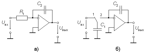
Fig. 1. Schemes of integrators: a) — on RC-circuit, b) — with switched capacitor
Figure 1 b shows the integrator, in which the resistor R1 is simulated using a switchable capacitor circuit. This integrator works as follows. The switch periodically switches from position 1 to position 2 and back to period T. At time nT the capacitor C1 is charged to the voltage uin (nT), so the charge accumulated on it is C1uin (nT). After switching the switch from position 1 to position 2 at the moment nT + T / 2, the capacitor C1 is discharged to the input of the op-amp with the capacitor C2 in the feedback. Since the input differential voltage and the input currents of the ideal op amp are zero, the capacitor C1 is discharged completely and its charge is summed with the charge accumulated on the capacitor C2. As a result, at the instant (n + 1) T the following equation of charges is valid:
Здесь знак "-" обусловлен отрицательной обратной связью. Применив к обеим частям уравнения (3) z-преобразование, получим уравнение
![]() (4)
(4)
The transfer function defined from this equation has the form
![]() (5)
(5)
It is of interest to compare the properties of integrators shown in Fig. 1. We pass to the frequency characteristics, substituting in (5) ![]() . We get
. We get
![]() (6)
(6)
When ![]() which tends to 0, the expression in parentheses in the denominator of the right-hand side of equation (6) approaches indefinitely
which tends to 0, the expression in parentheses in the denominator of the right-hand side of equation (6) approaches indefinitely![]() . Thus, for the frequencies of the input signal, low with respect to the switching frequency f = 1 / T, we can approximately write
. Thus, for the frequencies of the input signal, low with respect to the switching frequency f = 1 / T, we can approximately write
![]() (7)
(7)
Comparing expressions (2) and (7), we find that in the circuit in Fig. 1 b, a commutated capacitor simulates an input resistor of the circuit in Fig. 1a, with a resistance equal to. Therefore, by increasing the switching frequency of the commutation, we decrease the equivalent integration time constant of the integrator.
The use of integrators with switchable capacitors in IC filters instead of conventional integrators provides two significant advantages. First, the factor of transfer of the integrator depends only on the ratio of the two capacitors, and not on their absolute values. Generally speaking, it is quite easy to create a pair of any one-type matched elements on the silicon substrate of the IC, while the production of different types of elements (resistor and capacitor) with precise values and high stability is very difficult (the differences in the temperature coefficients of resistance (TCR) and capacitance (TKE) can be significant!). Therefore, IMS filters on switchable capacitors are much cheaper. For example, an 8th-order low-pass filter on the MAX291 IMS (switched capacitors) costs almost 5 times less than a similar filter on two MAX270 ICs (RC integrators).
The second advantage of filters on switched capacitors is the ability to adjust their characteristic frequency (i.e., the center frequency of the band pass filter or the -3 dB point of the low pass filter) by changing only the clock frequency. This is because the characteristic frequency of a filter constructed on the basis of the state variable method is proportional to the transfer coefficient of the integrator (or, what is the same, inversely proportional to the integration time constant). This allows the release of 8th order filters in an eight-pin package without external time-consuming elements (for example, MAX291), while IC filters with RC integrators have significantly more leads and require the connection of a significant number of accurate resistors (for example, the MAX274 chip has 24 pin, its typical circuit includes 15 external resistors).
Now about the disadvantages of filters on switched capacitors. Such filters have two unpleasant properties, which are due to the presence of a periodic clock signal. The first is through-passing the clock signal, namely the presence of some output signal (with a voltage of about 10 to 25 mV) with a clock frequency, the voltage of which does not depend on the applied input signal. Most often this is not significant, since this signal is significantly removed from the bandwidth occupied by the signal being processed (usually IC designers specify the switching frequency 100 times (rarely 50 times) higher than the characteristic frequency of the filters). If such pass-through of a clock signal is undesirable, a simple LPF of the first or second order is usually used to suppress it. The composition of IC filters on switched capacitors typically includes a non-inverting follower on which such a filter can be constructed.
The second problem of a more subtle property is related to the superposition of spectra. Any components of the input signal that are spaced in frequency from the frequency of the clock signal by an amount corresponding to the frequencies of the bandwidth will not be suppressed. For example, if the MAX291 is used as a low-pass filter with a cutoff frequency of 1 kHz (at a clock frequency of 100 kHz), all spectral components of the input signal in the range from 99 to 101 kHz will be converted to a frequency band from DC to 1 kHz. Therefore, in the event that there are noticeable components of frequencies close to the clock frequency in the spectrum of the input signal, a simple low-pass filter should be inserted before the input of the filter.
Almost any electronic circuit — from simple circuits on transistors and operational amplifiers and up to the most sophisticated digital and microprocessor systems — requires for its operation one or more stable sources of direct current. Simple unregulated power supplies such as «transformer — uncontrolled rectifier — low-pass filter» in many cases are not suitable, because their output voltage depends on the load current and the voltage in the network. Fortunately, it's easy to build a stable power source using negative feedback and comparing the output voltage with some constant reference voltage. Such stabilized power supplies are universal and can be made in the form of integrated microcircuits of voltage regulators.
As a rule, the regulating element of the IMS of voltage regulators is a bipolar or field-effect transistor. If this transistor works in the active mode, then the stabilizer is called linear (continuous), and if the regulating transistor works in the key mode — impulse.
The microcircuits of the power supplies belong to the so-called intelligent power devices, and then there are those who have a more or less complicated circuit for controlling them besides the power transistors. The fundamental difficulty in creating such devices is that the power transistors dissipate considerable energy, thereby causing the crystal to heat up with a significant temperature gradient. This dramatically degrades the stability of the control circuit nodes, such as the reference voltage source and the differential amplifier stage of the error. This chip (A723) contains a regulating transistor, connected in series between the unsterilized voltage source and the load, an error amplifier and a thermo compensated reference voltage source. The scheme turned out to be so successful that in the early 70s its output reached 2 million pieces per month! In terms of the mass application among analog ICs, linear integral voltage regulators stand in second place after operational amplifiers.
References:
- Lidovsky VI Information theory. — M., «Higher School», 2002–120 s.
- Metrology and radio measurements in telecommunication systems. Textbook for High Schools. / IN AND. Nefedov, V. I. Khalkin, E. V. Fedorov and others — M.: Higher School, 2001–383 p.
- Sapenko M. P. Measuring information systems. -. — Moscow: Energoatom publishes, 2005. — 440 p.
